What kind of value will Vector Engine provide for the Oil & Gas market?
Cost benefits of using improved HPC in Oil & Gas Domain
- Improve success rate in exploration (reduce failure/delay cost)
- Improve E&P by seismic modelling/imaging & reservoir simulation
- You will save $750M if you could improve drilling success rate by 5%
(Assumption: cost per drill is $100M)
300M from drilling success + 300M not being delayed
or
150M x 5 wells = $750M
- You will gain $250M if you could improve recovery factor by 2.5%
- 200M BBL x 2.5% x $50/BBL = $250M
- Improving imaging + recovery factors by 4D seismic / EOR
- In total $1B
Note: Numbers can vary depending on conditions
In the oil and gas industry, improving the success rate of exploration and improving Exploration and Production by seismic modeling/imaging & reservoir simulation are major challenges. NEC would like to contribute a computing resource for seismic & reservoir by NEC's HPC platform, NEC SX-Aurora TSUBASA. Seismic modeling/imaging & Reservoir simulation are a part of exploration. However, we think that it will create a big gain for the market.
Decrease Exploration Cost and Increase Recovery Factor with NEC
- Decrease exploration cost by reducing the dry hole cost through better and faster seismic modelling/imaging
- Increase recovery factor by better and faster reservoir simulation
- By achieving 30% higher resolution
- Empowered by 2x compute performance
(30% higher resolution per dimension: 1.3 x 1.3 x 1.3 ≈ 2.2)
NEC Vector Engine (10B) provides
- 2.1x performance compared to GPGPU (NVIDIA V100)
- 16x performance compared to Intel Gold 6148 (2socket) – 250% higher resolution!!
Again, higher resolution is only one factor. However NEC tested a performance of reservoir simulation and achieved a better performance compared to GPGPU and CPU.
In Collaboration with nag®
Regarding these performance test, we are thankful to the members of the Numerical Algorithms Group for extending their support by studying the vector architecture of NEC's Vector Engine and implementing an industry standard workload for reverse time migration (RTM) on Intel's CPU, NVIDIA's GPU and NEC's vector architectures.
They also performed enhancements to the programs through code-level tweaks and compiler level optimizations relevant to each architecture in order to bring out the best performance on each of them. Their effort has led to this unbiased performance evaluation of the most prevalent architectures in the Oil and Gas industry and helped benchmark the capability of NEC Vector Engine for workloads relevant to the Oil and Gas Industry.
Technical Benefits of using NEC HPC for Oil & Gas Applications
So, let's start our technical advantages when we use NEC HPC for Oil & Gas application.
Stencil Code
Stencil patterns require updates to each element in a multidimensional array by referring to its neighbour elements.

These codes requires significant performance of both computation and memory access, since they load a value of each element several times while they store a new value once.
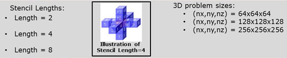
Stencil shapes and sizes differ based on the problem they solve:

At first we would like to talk about stencil Codes. The term Stencil refers to a pattern of data layout which is quite prominent in scientific computing for simulations and many other problems like image processing, signal processing and more recent frameworks for AI such as deep learning, etc. In a stencil layout, computation of each data element in a multidimensional array is done by referring to its neighboring elements. The number of neighboring elements to be referred is governed by the size of the stencil that is being computed.
In computer science terms, such updates require frequent access to the memory and require several loads from memory for a single store to the memory.
Here we can see several examples of varying stencil sizes over different dimensions that show the number of loads required for each store.
Reverse Time Migration (RTM)
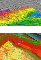
- Reverse time migration (RTM) modelling is a critical component in the seismic processing workflow of oil and gas exploration
- RTM imaging enables accurate imaging in areas of complex structures and velocities by gathering a two-way acoustic image of seismic data in place of a one-way image
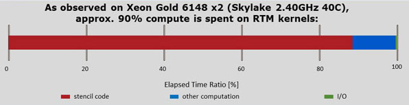
- RTM spends most of its computation time in wave propagation kernels that utilize stencil codes
- Full simulations of a generalized kernel called Anisotropic Elastic Wave Equation propagator can provide significant seismic information under a wide variety of geological assumptions
Having understood the importance of stencil codes and their compute and memory intensive attributes, we can now get a better understanding of the Seismic Imaging workloads relevant to the Oil and Gas industry.
Reverse Time Migration (RTM) modeling is a well-known critical component of seismic processing in Oil and Gas exploration. Given the programmatic design of a typical RTM workflow, stencil calculations take up a significant portion of the compute time. As observed on a 2-socket Intel Skylake based system, stencil calculations take up to 90% of the total compute time.
It hence becomes clear that for an enhanced performance on Seismic Imaging workloads, it is important to have a good performance on stencil calculations.
Fully Anisotropic Elastic Wave Equation Propagator
- The wave propagation kernels numerically represent the type of physics the user need to emphasize for the migration
- Isotropic acoustics is a common and simple wave propagation kernel for driving RTM, but with fewer assumptions on subsurface geology we obtain more accurate and expensive kernels like Vertical Transverse Isotropy (VTI) or Tilted Transverse Isotropy (TI)
- The elasto-dynamic wave equation for anisotropic media can be expressed as:
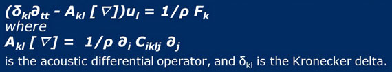
- This study covers both low frequency and high frequency fully anisotropic wave equation propagators
- Both propagators are relevant when considering Reverse Time Migration (RTM) and Full Waveform Inversion (FWI)
The wave propagation kernels numerically represent the physics required to emphasize on migration. In order to establish an understanding of the performance of an RTM program, we selected a fully anisotropic elastic wave equation propagator developed in C. Our study would cover both low frequency and high frequency propagation since they are both relevant to well known seismic workloads such as Reverse Time Migration and Full Waveform Inversion.
STREAM Benchmark – A Reference
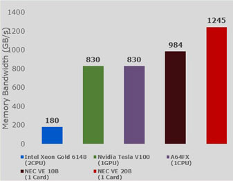
- STREAM benchmark evaluates memory bandwidth and is a good benchmark for preliminary comparison.
Comparison with Intel Xeon Gold 6148:
- On Intel machine STREAM Triad achieves 180 GB/s
- On NEC machine STREAM Triad achieves 984 GB/s
- Expected maximum speed-up on NEC – 984/180 = 5.5x
Comparison with NVIDIA Tesla V100:
- On NVIDIA machine STREAM Triad achieves 830 GB/S
- On NEC machine STREAM Triad achieves 984 GB/s
- Expected maximum speed-up on NEC – 984/830 0 1.2x
The calculated speed-up builds an expected result for the experiment.
Note: the depicted are obtained with proto version of NEC VE20B. The comparison will be further improved in the near future
A more practical understanding to the ideas discussed till now can be seen through the STREAM benchmark. The bar chart here captures the memory bandwidth recorded for several architectures using the well-known STREAM benchmark, and this can be a good reference to theoretically estimate speedups for memory-bound workloads. This chart covers Intel Skylake, NVIDIA Tesla V100, Arm A64FX (Fugaku) and NEC's Vector Engine.
When compared to Intel, a theoretical speedup of up to 5.5x can be expected considering the memory bandwidth capability. Similarly, for Tesla V100, a theoretically calculated expected speed-up is around 1.2x on NEC Vector Engine.
Evaluation Setup
Evaluation Target System
The evaluation target systems were chosen based on the below three popular HPC architectures:

Software Setup
The implementation of the anisotropic wave equation kernel that computes results for three problem sizes and three stencil lengths:
With the basis of experiment established, let me talk about the setup.
To setup the experiment, we arranged for 3 target systems:
- a 2-socket Intel Skylake CPU based system,
- a Vector Engine 10B single card based system, and
- an NVIDIA Tesla V100 single GPU card based system
For the software setup, we developed a program in C where we evaluated different stencil sizes of 2, 4 and 8 over varying data sizes from 64-cube through 256-cube. An illustration of Stencil length=4 is shown here for reference.
Evaluation Setup
- The core computation is timed where the timing results are an average of 10 iterations of the wave equation solver
- Code also computes min, max, standard deviation of timings but these are largely to certify the timing is sensible, i.e. if standard deviation is large the result is discarded and run again
- Each iteration is compared against an analytic solution to ensure correctness, but this comparison is not timed
- On an ideal system with perfect number of registers and caching, the stencil length would not change performance at all. However, with varying sizes of cache and vector registers, source code tuning was attempted across all architectures.
To evaluate the performance, we have timed 10 iterations of the wave equation solver. The program also computes minimum, maximum and standard deviation of these timings to gauge whether the timings are practical. In case the standard deviation for a specific run is too large, we discard the results and run again. This way we ensure fairness of evaluation. For correctness, each iteration is compared against an analytic solution in order to ensure correctness, but this comparison is not timed.
Ideally, from a pure software standpoint, the length of the stencil should not affect the performance at all. I mean if each hardware was developed with a perfect number of registers and caching, all stencil lengths would provide similar performance. However, with different hardware designs and varying register sizes and cache sizes, it is imperative that we tune the software in order to extract the best performance from the underlying hardware.
Source Code Modifications
| On Intel Xeon | On NEC VE | On NVIDIA V100 |
|
|
|
Similarly, there were some more subtle tweaks performed in the code for each target architecture, and the ones that resulted in good performance boost are listed in this slide.
For CPU centric codes, a simple re-ordering of loops helped, and blocking outer loops for cache optimization led to significant performance boost on the Intel Skylake systems. AVX512 instructions were also used.
For vector centric codes, a simple reordering of loops helped in faster vector performance. Collapsing two nested loops in order to ensure a single long vector helped utilize the long vector pipes better. Unrolling the outermost loops provided an additional boost to the performance, however the compiler was automatically able to perform the unrolling without the requirement of manual code modifications.
For GPU centric codes, the overall program was written in CUDA where the computations were offloaded to the device. Complicated if-else branches were simplified where the branching was relatively more intricate.
While more complicated tuning approaches posed scope for better performance impacts, we didn't lose our focus on the ease and simplicity of tuning for high performance.

Performance Results (1)
- For small problem sizes, NEC Vector Engine outperforms both CPU and GPU, although performing very similar to the GPU
- These small problem sizes also do not utilize the large data processing capability of the vector engine due to smaller vector lengths
- Smaller vector lengths provide better cache friendliness on CPUs and tend to perform well
- As expected, the speed-up is in the range of 3.5x ~ 4.5x for CPU, which is short of the expected theoretical speed-up based on memory bandwidth considerations
Finally, we recorded the timings as planned and plotted them on the bar chart as shown in this slide. Lower bars indicate faster timings.
For the relatively small problem size of 64-cube, NEC Vector Engine outperforms both the CPU and GPU, although GPU performance is competitive, especially for stencil size = 8, where GPU is slightly faster than VE. Since the problem sizes are small, they do not tend to utilize the large data processing capability of the vector engine due to smaller vector lengths. In fact, smaller vector lengths provide better cache friendliness on CPUs and tend to perform well.
The speed-up here on the Vector Engine is about 3.5x to ~ 4.5x of the CPU, which is short of the expected theoretical speedup based on memory bandwidth considerations.
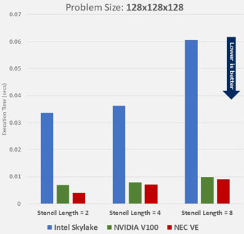
Performance Results (2)
- With increase in dataset sizes, the speed-up improves
- NEC Vector Engine still outperforms both the CPU and GPU based systems, with noticeable performance benefit compared to GPU
- The speed-up is in 6.0x ~ 8.5x range compared to CPU, which is a much better representative of the expected performance speed-up on theoretical bases
- NEC VE provides nearly 1.7x faster performance compared to GPUs
With increase in dataset sizes, the speedup improves. This slide shows the recorded timings for the 128-cube dataset.
NEC Vector Engine still outperforms both the CPU and GPU based systems, with a noticeable performance advantage compared to GPU.
The speedup is about 6 times to 8.5 times compared to CPU and is a much better representative of the expected performance speedup on theoretical bases.
NEC VE interestingly provides nearly 1.7x faster performance compared to GPUs, which is higher than the theoretically estimated performance.

Performance Results (3)
- Larger problem sizes speed-up brought up to 16.0x between Intel Xeon and NEC VE, much higher than the theoretical best speed-up of 6x based solely on memory bandwidth considerations
- Even for the NVIDIA GPU, the speed-up is in the 1.5x ~ 2.1x range, that is higher than the theoretical memory bandwidth consideration
- The speed-up suggests that the NEC VE provides a god combination of boosts in memory performance, as well as computational performance
With larger problem sizes observed speedups range as high as 16x between the Intel and NEC systems, much higher than the theoretical best speedup of 6x based solely on memory bandwidth considerations. There seem to be more factors at play here, such as cache limitations on the CPU for large dataset sizes.
Even for the NVIDIA GPU, the speedup is in the 1.5x ~ 2.1x range, higher than the theoretical memory bandwidth consideration.
The speedup suggests that the NEC Vector Engine provides a good combination of boosts in memory performance, as well as computational performance.
Performance Results (4)
- This plot represents the number of grid-points being evaluated per-second for each architecture
- NEC Vector Engine consistently outperforms the CPU and GPU architectures, up to 16x faster than Intel Skylake, and more than 2x faster than NVIDIA V100 for large datasets
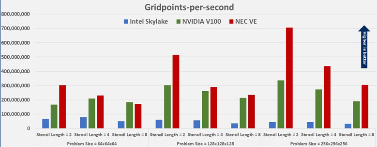
Having observed the timings and speed-ups obtained on the Vector Engine, we also evaluated the performance based on the number of grid points calculated per second on each architecture for the same stencil sizes and dataset sizes. Here we get a clearer picture of how the Vector Engine consistently outperforms the CPU and GPU architectures, by calculating up to 16x more grid points than Intel Skylake, and in some cases more than 2x more grid points than NVIDIA V100 for large datasets.
Performance Results (5)
| Intel Skylake Gold 6148 | NVIDIA Tesla V100 | NEC VE Type 10B | |
| Stencil Length = 2 | 64-grid | 256-grid | 256-grid |
| Stencil Length = 4 | 64-grid | 256-grid | 128-grid |
| Stencil Length = 8 | 64-grid | 256-grid | 256-grid |
This table can help a developer design the granularity of parallelism for their code based on what architecture they are working on.
For each stencil length, VE is consistently the best in terms of choice of grid size for each architecture.
In fact, the performance patterns observed here, also reveal the ideal grid size based on best performance per-core for each architecture. This table can serve as a reference to developers and help them design the granularity of parallelism, i.e. the distribution of grid size per core for their code based on what architecture they are working on. For each stencil length, VE is consistently the best in terms of choice of grid size for each architecture.
Summary of Performance Results (5)
- Stencil codes are performance intensive on the memory as well as compute for any given architecture
- Reverse Time Migration is a performance intensive code, especially memory bound and poses a genuine challenge relevant to the Oil and Gas industry
- Vector architectures, particularly the NEC Vector Engine is capable of catering to the recurring challenges in seismic processing and providing better performance than the available leading architectures
- Power efficient solution with minimal software engineering effort
To summarize this talk, we learned that stencil codes are performance intensive on the memory as well as compute for any given architecture.
Seismic Imaging (particularly Real Time Migration) is a performance intensive code, especially memory bound and poses a real problem relevant to the Oil and Gas Industry.
Our experiments establish the initial claim that Vector Architectures, particularly the NEC Vector Engine through its high memory bandwidth and computational capacity is capable of catering to the recurring challenges for prominent applications in seismic processing and providing better performance than the available leading architectures, with lower power consumption and reduced software engineering effort.
Other Report
RTM Scalability (study by Federal University of Rio de Janeiro)
SX-Aurora TSUABASA shows good performance and scalabiltywith less numbers of cores
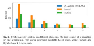
This slide shows another report about RTM scalability studies by the Federal University of Rio de Janeiro.
In this chart, lower is better, and you can see SX-Aurora TSUBASA, the blue bar is showing good performance and scalability compared to Xeon processors depict in orange and green bars. Prof. Alvaro Coutinho stated "The NEC SX-Aurora TSUBASA vector system proved to be an excellent technology for enabling our workflow for seismic imaging under uncertainty". For details, please see his paper.
Conclusion
Conclusion of NEC HPC.
3 Reasons why you want to use the Vector Engine
- Good Balance of compute power and memory capability
- 307 GF/core, 2.45 TF/processor
- 48 GB HBM2 memory on board, 1.53 TB/s mem bandwidth
- Big core delivers high sustained performance
- Easy to start
- Start small and scale large
- Standard programming (Fortran, C, C++)
- Good for seismic modelling and reservoir simulation
- VE is a good fit for Oil & Gas applications which require large memory bandwidth
- Shorter computation time and more accurate results
NEC's Vector Engine provides a good balance of compute power and memory capacity for image processing, signal processing and situation of requiring a matrix calculation.
Also, you can start with a small system and then expand to large scale system, easily.
Especially in seismic modeling/imaging and reservoir simulation, you can get shorter computation time.
We believe that this will save time and improve the success rate of discoveries, resulting in cost reductions or increased profits through efficient mining through detailed simulations.
Find more Information on our Website
If you are interested in NEC's HPC platform, you can find more information about our hardware, software, and supported applications on our SX-Aurora TSUBASA website. Thank you!
- Intel and Xeon are trademarks of Intel Corporation in the U.S. and/or other countries.
- NVIDIA and Tesla are trademarks and/or registered trademarks of NVIDIA Corporation in the U.S. and other countries.
- Linux is a trademark or a registered trademark of Linus Torvalds in the U.S. and other countries.
- Proper nouns such as product names are registered trademarks or trademarks of individual manufacturers.